Installation of a Lonestar System.
This document details the installation of the hardware for a standalone Lonestar system. The software used to control the Lonestar system is detailed in the document “Lonestar Software for Standalone Systems”.
Once the Risk Assessments have been performed and a suitable site for the location of the Lonestar has been determined, remove the Lonestar from its peli-case. Place the Lonestar system on a solid, level surface capable of supporting its weight. Remove the Cole Palmer filter and other equipment from the packaging and check against the packing list to be sure that everything has been despatched.
Typically, standalone Lonestar units are used in conjunction with a pump to draw the sample through the inlet. Certain pumps can be controlled via the Lonestar software; please consult the Owlstone Support staff for compatible pumps and to give advice on required specifications. Care must be taken with the choice of pumps as explosive mixtures may occur, so an explosive-proof pump must be purchased if required, depending upon the sample type.
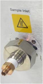 |
The Cole Palmer inlet filter supplied with the Lonestar must be fitted to the inlet of the Lonestar. This is to prevent particles >1µm in diameter from entering the Lonestar, possibly causing damage to the FAIMS chip.
|
|
|
|
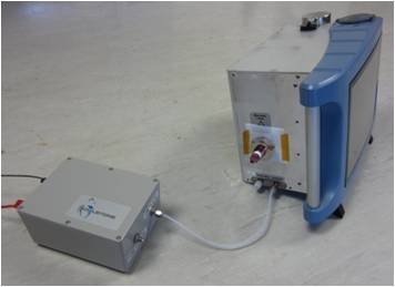 |
The pump inlet is connected to the Lonestar exhaust fitting, so the sample gas will be drawn through the Lonestar and subsequently through the pump.
|
|
|
|
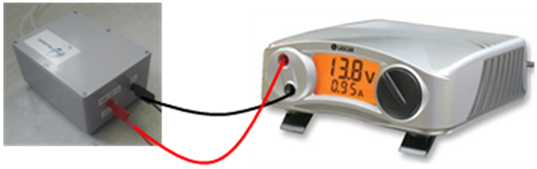 |
Connect the pump to a variable voltage power supply. |
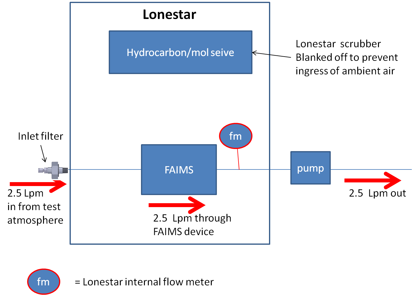
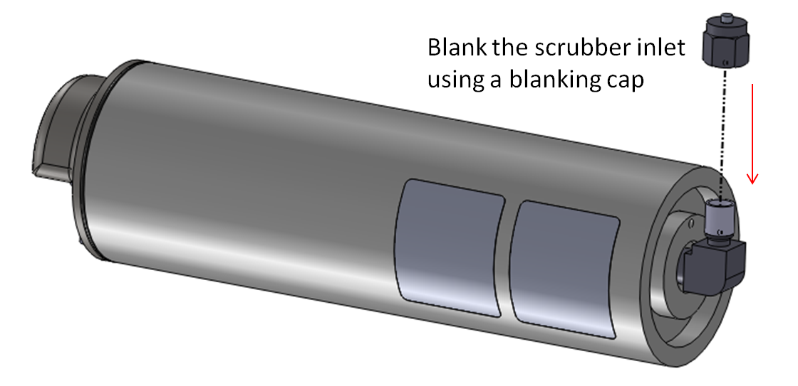
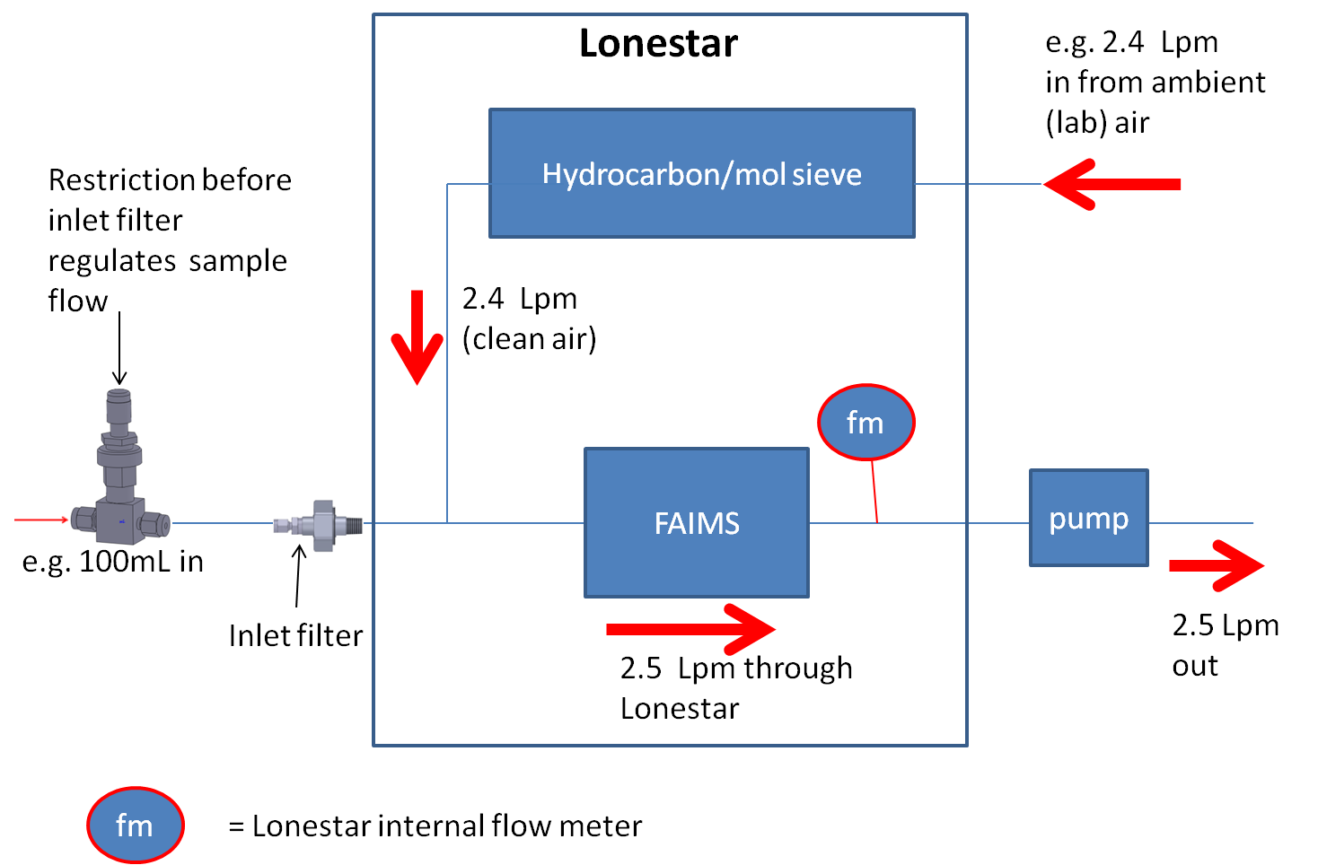
This is the simplest installation of the standalone Lonestar system. The flowpath is summarised below with a pump drawing sample air only, with no dilution of the sample flow with cleaned ambient air. The Lonestar scrubber must be blanked to prevent ingress of ambient air into the system. A total of 2.5Lpm used for example purposes only.
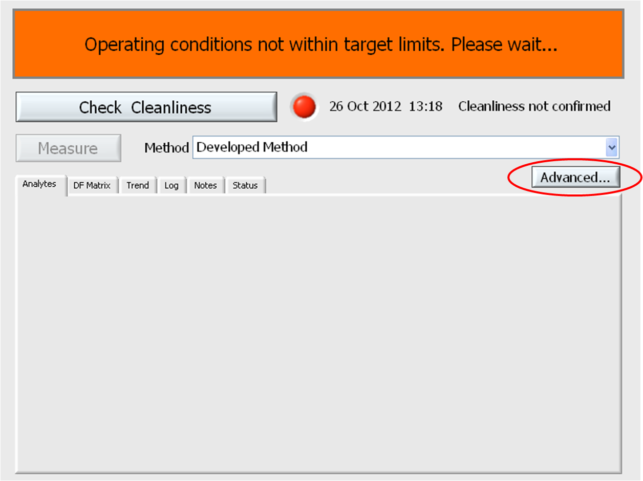
Once the hardware has been installed, turn on the Lonestar system. The Lonestar system starts in Analyser Mode by default, but this mode of software operation is for developed methods rather than for method development. Press the Advanced button to view the Lonestar parameters.
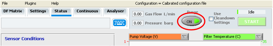
The Purge must be set ON to align the Lonestar internal flowpath for use with a pump.
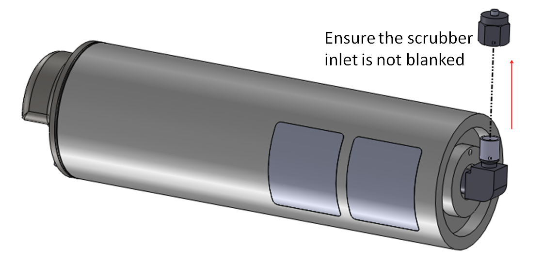
If, in this setup, the concentration of the analyte being monitored is too high at the Lonestar (loss of RIP suggesting system saturation has occurred), then a restriction can be placed before the inlet filter. This restriction may be a needle valve, a rotameter, a mass-flow controller or a fixed orifice. In the example below, a needle valve is shown. The Lonestar scrubber must not be blanked in this setup to allow the scrubber to clean ambient air, which dilutes the sample flow.
This document is available to download as a .pdf for printing, see the link below:
Comments
Please sign in to leave a comment.