Split box consists of 3 mass flow controllers (MFC); 2 capable of up to 500mL min-1 flow rates and 1 capable of 3L min-1 flow rates. They are arranged as shown below.
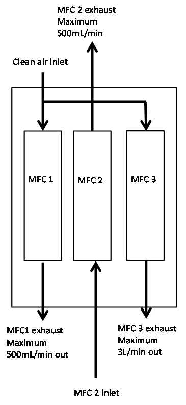
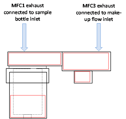
MFC1 and MFC3 exhausts should be set up to At-line sample module using 1/8” PTFE pipe as shown in Figure a. If MFC2 is required the inlet should be connected to the split port on the At-line sampling module as shown in Figure b.
(a)
(b)
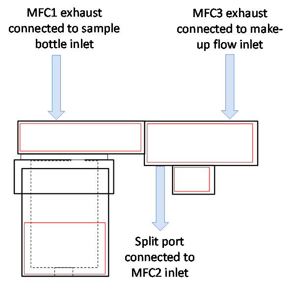
a): Connections to At-line sampling module and (b): connections to At-line sampling module with added split flow.
Comments
Please sign in to leave a comment.